Inverted pendulum
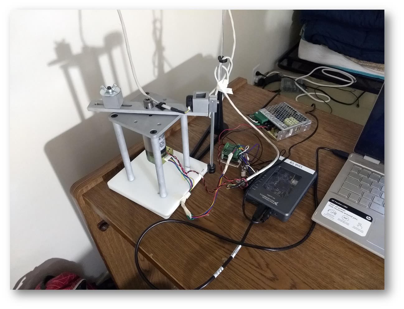
Swing-up and stabilisation of a multi-degree-of-freedom inverted pendulum on hardware I built the driver for: bring the rod up from hanging, then hold it upright against whatever you do to it.
The problem
An inverted pendulum is the standard hard case in controls for a reason: the plant is unstable in open loop, the thing you can actuate (the cart) is not the thing you care about (the rod angle), and the two are coupled through a nonlinearity that only behaves near the upright. Left alone, it falls. Every time.
Approach
Two controllers rather than one. Away from the upright the system runs a swing-up law that pumps energy into the rod until its total energy matches the upright equilibrium; near the upright, control hands off to an LQR balance loop designed on the linearised multi-DOF model. The interesting engineering is the handover — the switching region has to be wide enough to catch the rod reliably and tight enough that the linear model is still honest.
Down to the driver
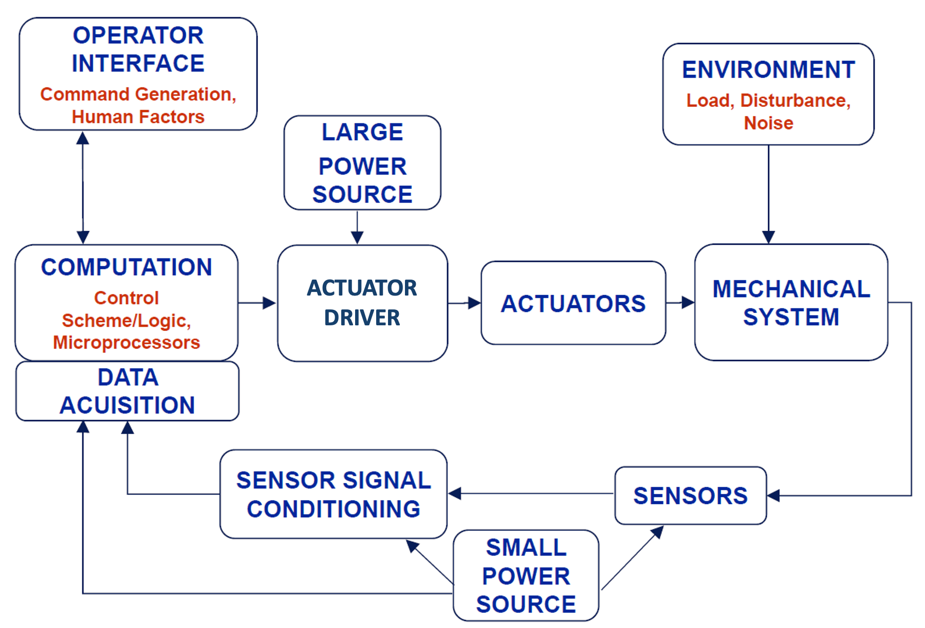
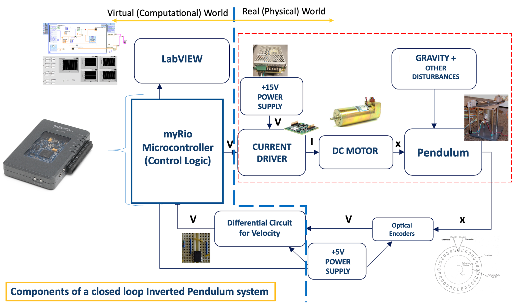
The current driver is self-designed rather than bought, which means the motor's behaviour is a design variable rather than a datasheet. Plant parameters were identified three ways — from CAD, from a dynamometer, and from oscilloscope measurement — so the model the controller was designed against had more than one source of truth behind it. Everything runs on a National Instruments myRIO with an optical encoder closing the loop.
What it does
From rest, the cart drives the rod up and catches it. Push the rod by hand and the cart moves under it to recover. The video below is the whole argument.
Specification
- Actuation
- DC motor driven by a self-designed current driver, with speed and position control
- Sensing
- Optical encoder
- Modelling
- MATLAB and Simulink
- Controller
- Linear quadratic regulator (LQR)
- Target
- National Instruments myRIO
- Parameter ID
- CAD, dynamometer and oscilloscope measurement
On the bench